How
Gears Work
by
Marshall
Brain
 You see gears in just about everything that has spinning parts. For
example, car engines and transmissions contain lots of gears. If you
ever open up a VCR and look inside you will see it is full of gears.
Wind-up, grandfather and pendulum clocks
contain plenty of gears, especially if they have bells or chimes. You
probably have a power meter on the side of your house, and if it has
a see-through cover you can see that it contains 10 or 15 gears.
Gears are everywhere where there are engines and motors producing
rotational motion. In this edition of How Stuff Works you will
learn about gears, gear ratios and gear trains so that you can
understand what all the different gears you see are doing.
You see gears in just about everything that has spinning parts. For
example, car engines and transmissions contain lots of gears. If you
ever open up a VCR and look inside you will see it is full of gears.
Wind-up, grandfather and pendulum clocks
contain plenty of gears, especially if they have bells or chimes. You
probably have a power meter on the side of your house, and if it has
a see-through cover you can see that it contains 10 or 15 gears.
Gears are everywhere where there are engines and motors producing
rotational motion. In this edition of How Stuff Works you will
learn about gears, gear ratios and gear trains so that you can
understand what all the different gears you see are doing.
Gears are generally used for one of four different reasons:
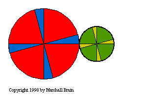
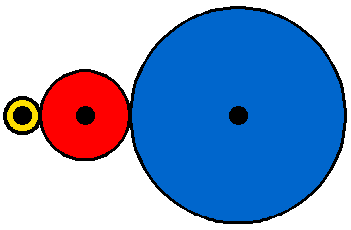
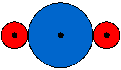
You can see effects 1, 2 and 3 in the figure to the left. In this
figure, you can see that the two gears are rotating in oposite
directions, that the smaller gear is spinning twice as fast as the
larger gear, and that the axis of rotation of the smaller gear
is to the right of the the axis of rotation for the larger gear. The
fact that one gear is spinning twice as fast as the other results
from the ratio between the gears, or the gear ratio. In
this figure, the diameter of the gear on the left is twice that of
the gear on the right. The gear ratio is therefore 2:1 (pronounced,
"Two to one"). If you watch the figure you can see the ratio: Every
time the larger gear goes around once the smaller gear goes around
twice. You can see that if both gears had the same diameter, they
would rotate at the same speed but in opposite directions.
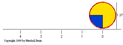
Understanding the concept of the
gear ratio is easy if you understand the concept of the
circumference of a circle. Keep in mind that the circumference
of a circle is equal to the diameter of the circle multiplied by
Pi (Pi is equal to 3.14159...). Therefore, if you have a
circle or a gear with a diameter of one inch, the circumference of
that circle will be 3.14159 inches. The following figure shows how
the circumference of a circle with a diameter of 1.27 inches is equal
to a linear distance of 4 inches:
Let's say that you had another circle whose diameter was
1.27 inches / 2
= 0.635 inches, and you rolled
it in the same way as in this figure. You would find that, because
its diameter is one half of the circle's in the figure, it has to
complete 2 full rotations to cover the same 4 inch line. This
explains why two gears, one half as big as the other, have a gear
ratio of 2:1. The smaller gear has to spin twice to cover the same
distance covered when the larger gear spins once.
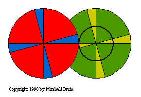
Most gears that you see in real life have teeth. The teeth have three advantages:
To create large gear ratios, gears
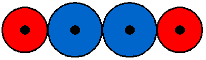
are often connected together in gear trains as shown here:
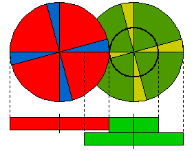
The right-hand (green) gear in the train is actually made in two
parts, as shown. A small gear and a larger gear are connected
together, one on top of the other. Gear trains often consist of
multiple gears in the train, as shown in the following two
figures:

In the case above, the green gear turns at a rate twice that of the
red gear. The blue gear turns at twice the rate as the green gear.
The yellow gear turns at twice the rate as the blue. The gear train
shown below has a higher gear ratio:
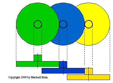
In this train, the smaller gears are 1/5th the size of the larger
gears. That means that if you connect the green gear to a motor
spinning at 100 RPMs (Revolutions Per Minute), the blue gear will
turn at a rate of 500 RPMs and the yellow gear will turn at a rate of
2,500 RPMs. In the same way, you could attach a 2,500 RPM motor to
the yellow gear to get 100 RPMs on the green gear. If you can see
inside your power meter and it is of the older style with 5
mechanical dials, you will see that the 5 dials are connected to one
another through a gear train like this, with the gears having a ratio
of 10:1. Because the dials are directly connected to one another,
they spin in opposite directions (you will see that the numbers are
reversed on dials next to one another).
There are many other ways to use gears. For example, you can use conical gears to bend the axis of rotation in a gear train by 90 degrees. The most common place to find conical gears like this is in the differential of a rear-wheel-drive car. A differential bends the rotation of the engine 90 degrees to drive the rear wheels:
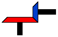
Another specialized gear train is called a planetary gear train. Planetary gears solve the following problem. Let's say you want a gear ratio of 6:1. One way to create that ratio is with the following three-gear train:
In this train, the red gear has 3 times the diameter of the yellow gear, and the blue gear has two times the diameter of the red gear (giving a 6:1 ratio). However, imagine that you want the axis of the output gear to be the same as that of the input gear. A common place to need this same-axis capability is in an electric screwdriver. In that case you can use a planetary gear system, as shown here:
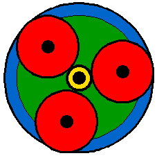
In this gear system, the yellow gear engages all three red gears simultaneously. They are all three attached to a plate (green), and they engage the inside of the blue gear instead of the outside. Because there are three red gears instead of one this gear train is extremely rugged. The ouput shaft is taken from the green plate, and the blue gear is held stationary. You can see a picture of an two-stage planetary gear system on the electric screwdriver page.
Finally, imagine the following situation: you have two red gears that you want to keep synchronized, but they are some distance apart. You can place a big gear between them if you want them to have the same directions of rotation:
Or you can use two equal-sized gears if you want them to have opposite rotational direction:
However, in both of these cases the extra gears are likely to be heavy and you need to create axles for them. In these cases the common solution is to use either a chain or a toothed belt, as shown here:

The advantages of chains and belts are light weight, the ability to separate the two gears by some distance, and the ability to connect many gears together on the same chain or belt. For example, in a car engine the same toothed belt might engage the crankshaft, two camshafts and the alternator. If you had to use gears in place of the belt it would be a lot harder!
Copyright © 1998-2000
Howstuffworks.com, Inc. All rights reserved.